Valves
- Home
- Products
- Fluid Handling
- Valves
Valves
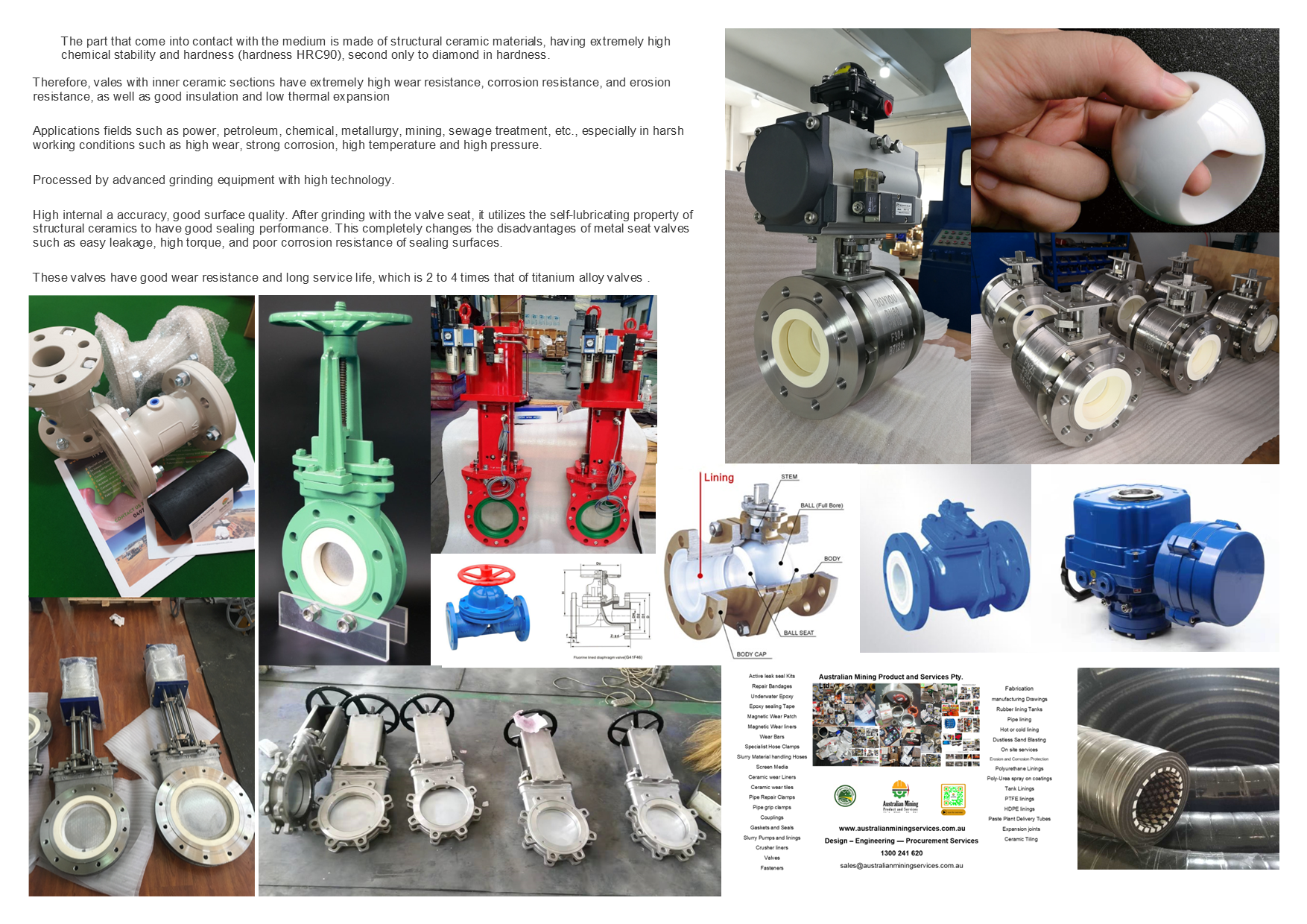

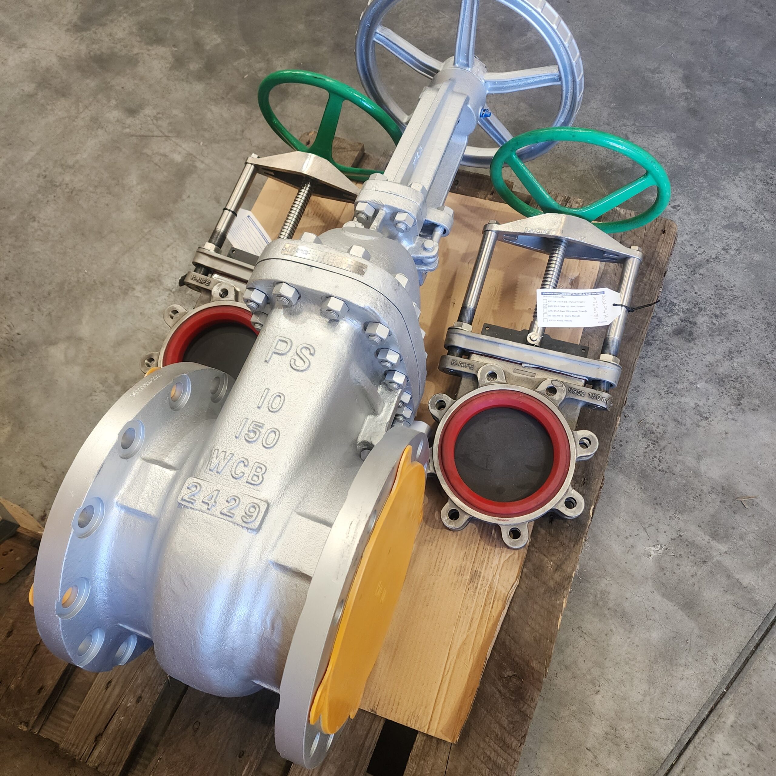
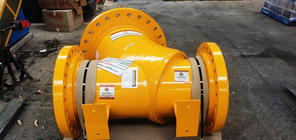
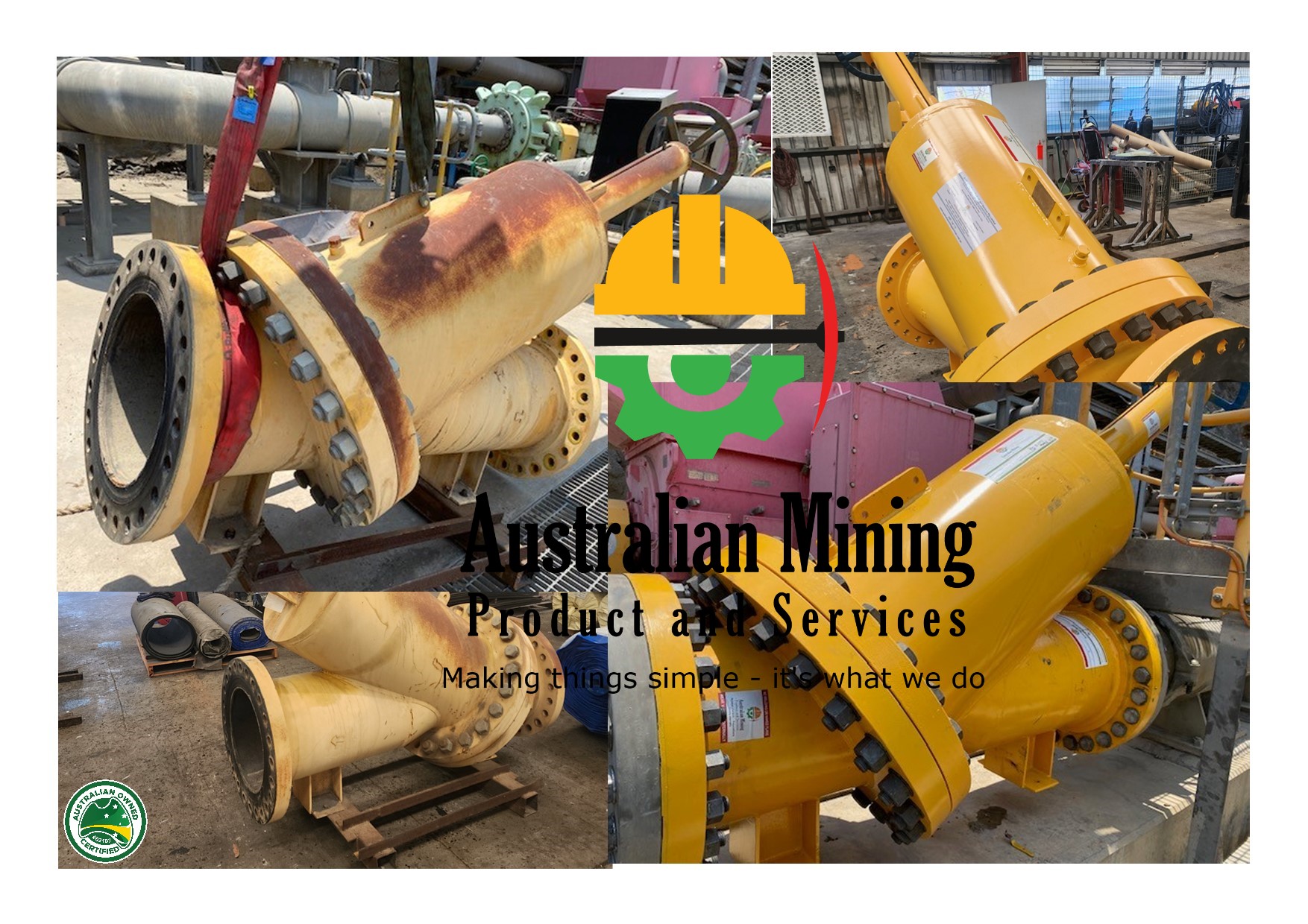
An outside Screw and yoke Gate valve and how is it different from a normal Gate valve?
The designation has to do with the location of the screw nut and the shaft screw threads.
Different Valve Types, Applications & Suitability
There are a large variety of valves and valve configurations to suit all services and conditions; different uses (on/off, control), different fluids (liquid, gas etc; combustible, toxic, corrosive etc) different materials and different pressure and temperature conditions. Valves are for starting or stopping flow, regulating or throttling flow, preventing back flow or relieving and regulating pressure in fluid or gaseous handling applications. Common valve types include: Ball,Butterfly,Check, Diaphragm, Gate, Globe, Knife Gate, Parallel Slide, Pinch, Piston, Plug, Sluice, etc.
The following types of valves are used in a variety of applications, these descriptions may provide a basic guideline in the selection of valves.
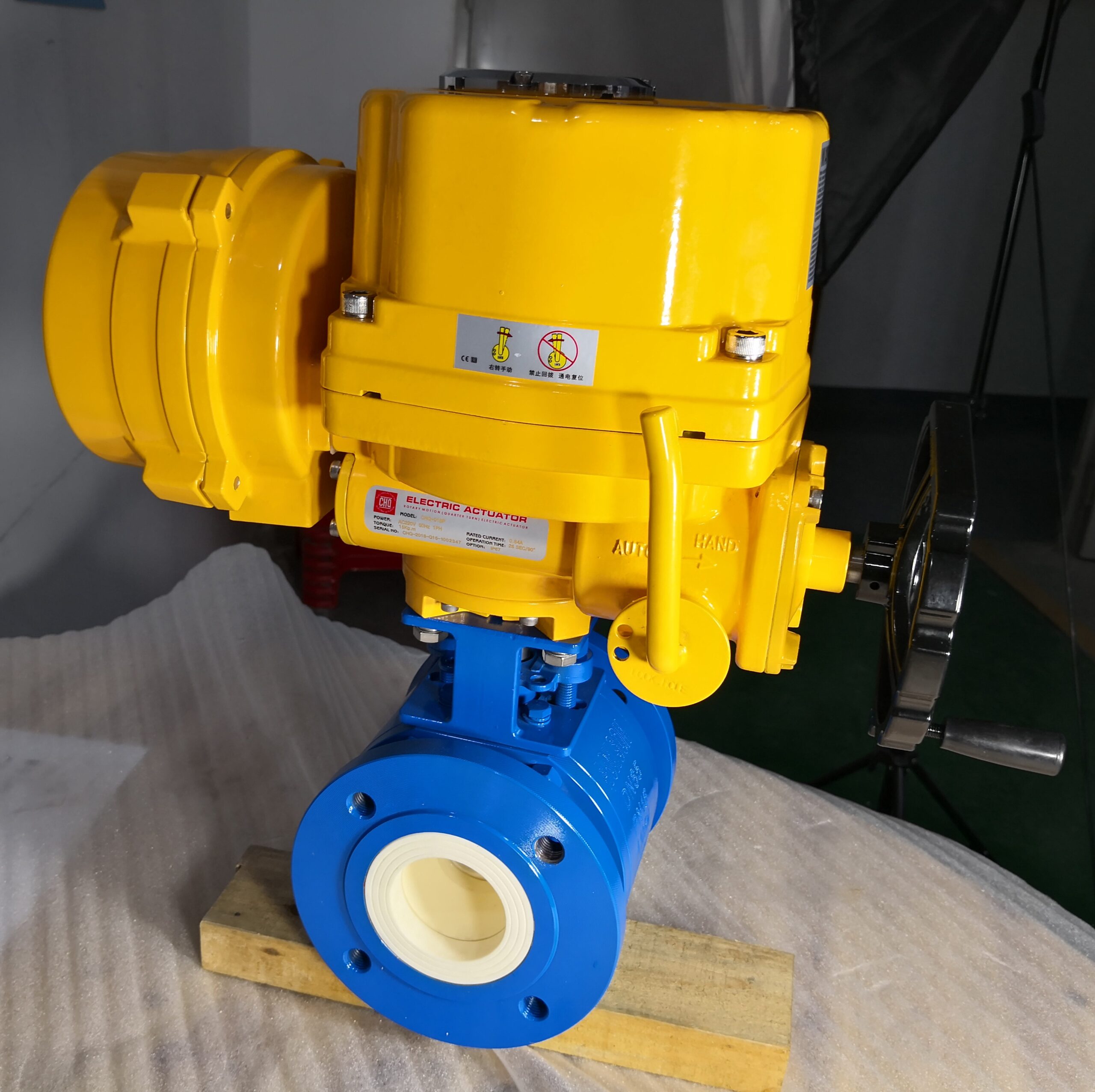
BALL VALVES
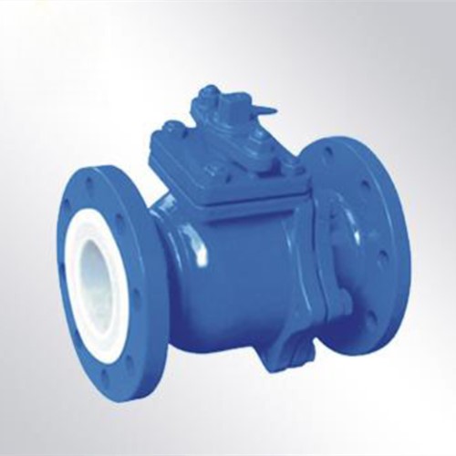
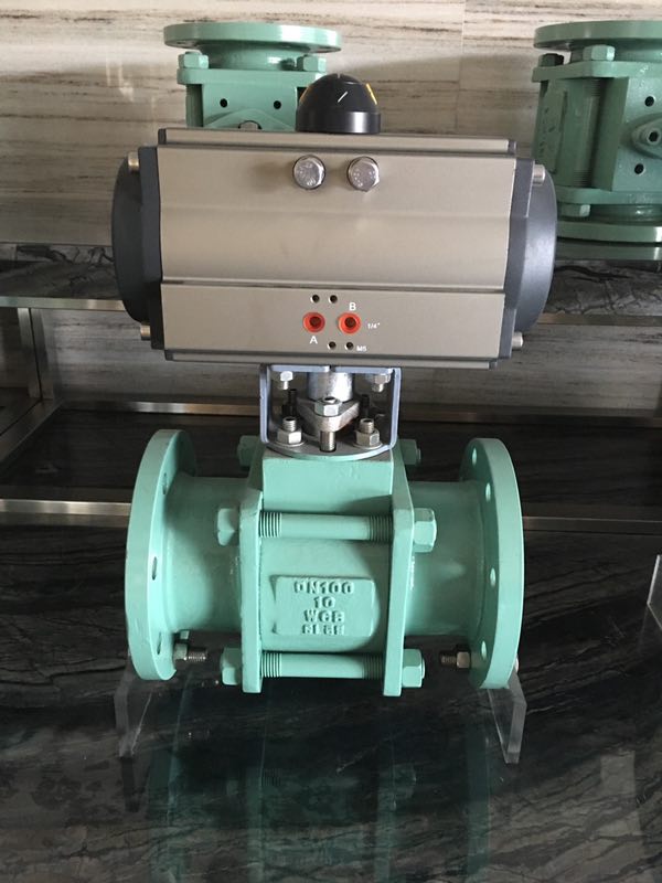
Because of their excellent operating characteristics, ball valves are used for the broadest spectrum of isolation applications and are available in a wide range of sizes and materials and are available in full fl ow and full through conduit. Advantages – quick acting, straight through fl ow in either direction, low pressure drop, bubble tight shut off & operating torque, easily actuated. Disadvantages – temperature limitiations on seating material, long “relative” face to face dimension.
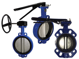
The butterfly valve derives its name from the wing-like action of the disc which operates at right angles to the fl ow. It’s main advantage is a seating surface which is not critical. It is designed for fl ow isolation. The disc impinges against a resilient liner to provide bubble tightness with low operating torque. Compact and with a simple construction, butterfly valves facilitate easy pipe arrangement. Due to disc, they have slightly reduced fl ow characteristics. Advantages – quick acting, good regulating characteristics, compact & light, low pressure isolation. Butterfly valves are simple, reliable and range in size from 40mm to 1000mm and beyond. They can be controlled by a notched lever, handwheel as well as by pneumatic or electric actuator. A shaft turns a disc 90º within a pipe. The disc angle within the pipe can provide a restriction varying from drip-tight through to almost full fl ow (except very small sizes).
Sometimes referred to as a non-return valve, the check valve prevents back-flow in the piping by constantly keeping fluid flowing in one direction. Check valves operate automatically. Some piston/disc check valves are spring loaded for fast operation, (minimum cracking pressure should be specified). Vertical downwards flow requires a spring loaded check valve.
Swing Check Valves: – Swing & Wafer checks cease reverse flow with a flap that swings onto a seat. Use swing checks only for forward flow that is horizontal or vertical upward.
Piston Check Valves: – Piston & Spring checks cease reverse flow with a spring loaded plunger.
Ball Check Valves:– Ball checks have a ball that slides into a hole as forward flow slows. Consider a ball check for semi-solids such as pulp or effluent.
Titlting Disc Check Valves: – Tilting Disc check valves are similar to Swing check valves but in most installations, slamming is minimised upon reversal of fl ow so noise and vibration are reduced.
Globe Valves
Globe/Stop Valves: – The flow path through globe valves follows a changing course, thereby causing increased resistance to flow and considerable pressure drop. Because of the seating arrangements, globe valves are the most suitable for throttling flow, however, avoid extremely close throttling when the repeatable pressure drop exceeds 20%. Close throttling creates excess noise, vibration and possible damage to valves and piping. for special service valve solutions. The valve is named after is globular body.
Compared to gate valves, globe valves are designed to open and close more quickly. Their flow characteristics can be changed by re-configuring their discs. Advantages – best shut off (not drip tight above 50NB) & regulating. Disadvantages – high pressure drop (head loss), unidirectional.
Stop Check Valves (SDNR): – Stop check valves are essentially the same as Globe valves, except there is no mechanical connection between the stem and the disc. They provide a combination Stop valve and a Piston check valve in one valve. However, they are not designed for throttling. They are used in steam boiler outlet piping when two or more boilers are connected to a common header. Valves must be installed with pressure under the disc, and when the stem is raised, only boiler pressure can raise the disc whenever boiler pressure exceeds header pressure. They prevent backflow from the header to boiler.
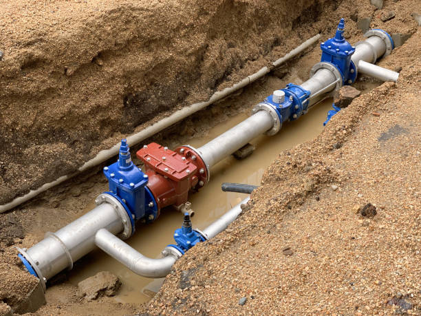
Gate Valves
Wedge Gate Valves: – Commonly used in industrial piping for stop or isolating – to turn on and shut off the flow as opposed to regulating flow.
Gate valves are named after the gate-like disc which operates at a right angle to the path of the flow.
Gate valves are general service valves that can be made in a broad spectrum of sizes using a variety of different materials.
Wedge gate valves are metal seated but are also available with resilient seat insert if drip tight shut off is required. They can meet the demands of a wide range of pressure and temperature conditions and is available in full port.
Advantages – low pressure drop, straight through flow either direction. Disadvantages – slow acting, bulky. Not drip tight shut off (over 150NB). Do not partially open as this will cause damage to the seat/disc.
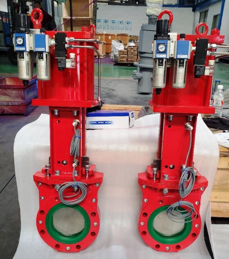
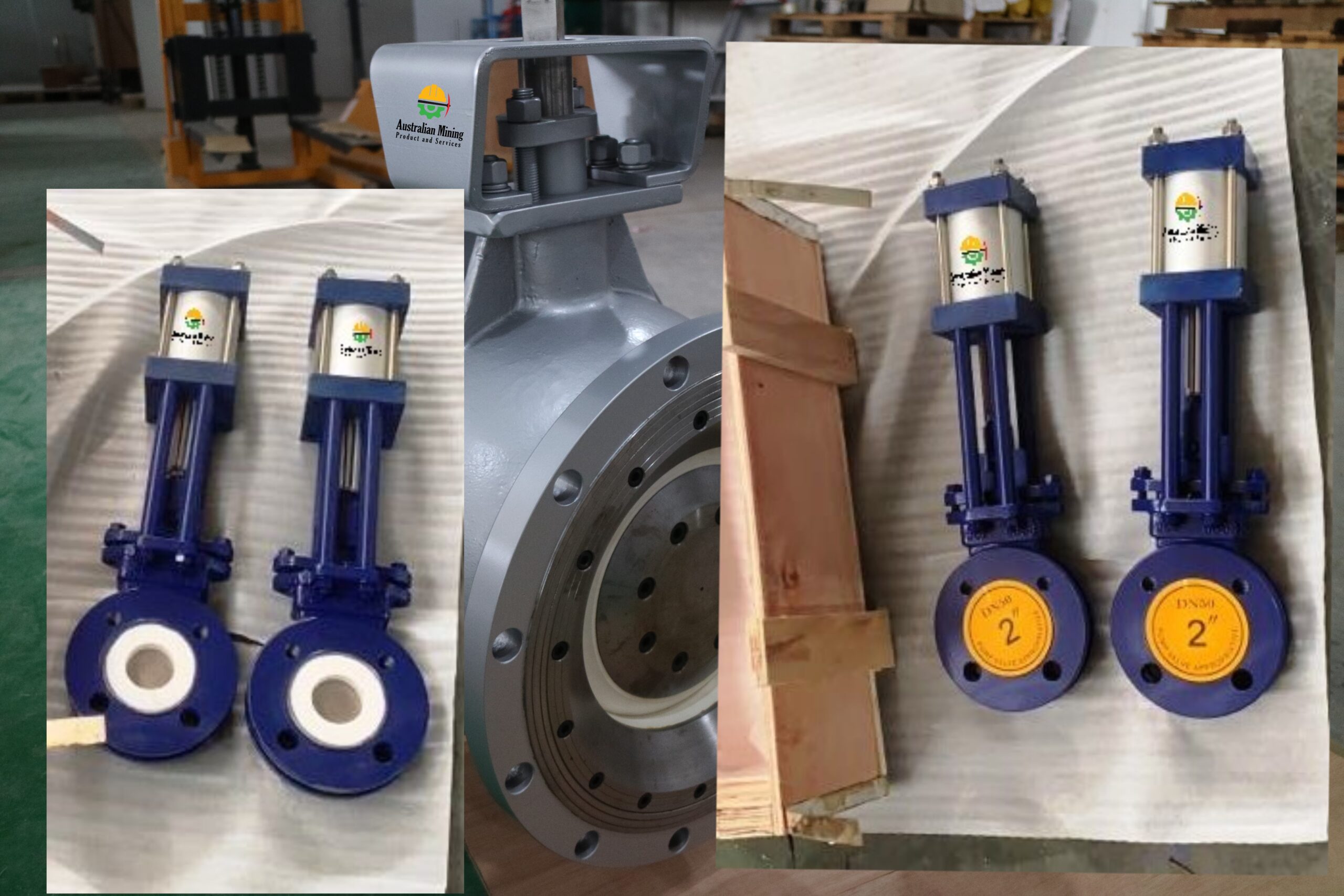
Knife Gate Valves: – Useful for many applications in larger-sized pipework (50mm up). Unlike traditional gate valves, they are able to throttle (at lower pressures) depending on line media and degree of opening. Metal seated knife gate valves are not leak tight shut off. Some knife gate valves have a resilient seat in order to ensure they close drip-tight. Available in v-port, o-port and lined they are ideally suited for the control of effluent, slurries, waste products, semi solids, pulp, bulk powders. Most knife gate valves are designed for single flow direction.
Parallel Slide Gate Valves: – Popular in steam applications as the energised disc design handles thermal expansion without sticking like wedge gate valves. Another advantage is lower torque then wedge gate valves especially in venturi (Ferranti) reduced bore configuration. Parallel slide valves consist of two parallel gates that are energised against the seat at all times by springs or a wedging spreader bar between the two gates. No mechanical stress is exerted between the discs, and the valve is not subjected to dangerous strains in opening and closing.
This design of valve maintains fluid-tightness without the aid of wedging action. These valves are used for saturated and super heated steam.
Pipeline Slab Gate Valves: – Available in parallel solid slab and expanding 2 piece wedging slab. Both styles protect the seat area from the flow in all operating positions. These valves have a full through conduit configuration with a hole in the slab. Slab style gate valves have seats that are spring energised. The expanding slab features two opposed sliding v-shape segments that maintain pressure against the seats. These valves are for API6D pipeline applications but are also used for API6A wellhead valves. All these valves are made in metal to metal and soft seat configuration.
Plug Valves
Butterfly Valve –
Wafer Type Butterfly Valve With PINS
Description
- Design and Manufacture Conform to EN593, API609
- Flange dimensions Conform to EN1092-2/ANSI B16.1
- Face to Face dimensions Conform to EN558-1
- Testing Conform to EN12266-1, API 598
- Driving mode: lever, worm actuator, electric, pneumatic
Specification
| NO. | Part Name °C | Material | Optional Material °C |
| 1 | Body | DI | CI, WCB, Stainless Steel |
| 2 | Down Bearing | F4 | Bronze |
| 3 | Seat | NBR | EPDM, FKM |
| 4 | Disc | Plated Ductile Iron | ASTM A351 CF8/CF8M, B148 C954/C958 |
| 5 | Shaft | ASTM A276 416 | 304, 316, 17-4PH |
| 6 | Middle Bearing | F4 | Bronze |
| 7 | Upper Bearing | F4 | Bronze |
| 8 | O Ring | NBR | EPDM, FKM |
| 9 | Pin | ASTM A276 416 | 316, 17-4PH, Monel |
Dimensions data(mm)
| DN | A | B | C | H | ΦE | ΦF | N-ΦK | Φd | G | EN1092-2 PN10 | EN1092-2 PN16 | ANSI CLASS 125 | ||||||
| ΦD | n-Φd1 | n-M | ΦD | n-Φd1 | n-M | ΦD | n-Φd1 | n-M | ||||||||||
| DN40 | 120 (140) | 75 | 33 | 32 | 90 | 50 | 4-Φ7 | 12.6 | 9.5 | 110 | 4-Φ19 | 4-M16 | 110 | 4-Φ19 | 4-M16 | 98.5 | 4-Φ16 | 4-1/2″ |
| DN50 | 124 (161) | 80 | 43 | 32 | 90 | 50 | 4-Φ7 | 12.6 | 9.5 | 125 | 4-Φ19 | 4-M16 | 125 | 4-Φ19 | 4-M16 | 120.5 | 4-Φ19 | 4-5/8″ |
| DN65 | 134 (175) | 89 | 46 | 32 | 90 | 50 | 4-Φ7 | 12.6 | 9.5 | 145 | 4-Φ19 | 4-M16 | 145 | 4-Φ19 | 4-M16 | 139.5 | 4-Φ19 | 4-5/8″ |
| DN80 | 141 (181) | 95 | 46 | 32 | 90 | 50 | 4-Φ7 | 12.6 | 9.5 | 160 | 8-Φ19 | 8-M16 | 160 | 8-Φ19 | 8-M16 | 152.5 | 4-Φ19 | 4-5/8″ |
| DN100 | 156 (200) | 114 | 52 | 32 | 90 | 70 | 4-Φ10 | 15.8 | 11.1 | 180 | 8-Φ19 | 8-M16 | 180 | 8-Φ19 | 8-M16 | 190.5 | 8-Φ19 | 8-5/8″ |
| DN125 | 168 (213) | 127 | 56 | 32 | 90 | 70 | 4-Φ10 | 18.92 | 12.7 | 210 | 8-Φ19 | 8-M16 | 210 | 8-Φ19 | 8-M16 | 216 | 8-Φ22 | 8-3/4″ |
| DN150 | 184 (226) | 140 | 56 | 32 | 90 | 70 | 4-Φ10 | 18.92 | 12.7 | 240 | 8-Φ23 | 8-M20 | 240 | 8-Φ23 | 8-M20 | 241.5 | 8-Φ22 | 8-3/4″ |
| DN200 | 213 (260) | 175 | 60 | 45 | 125 | 102 | 4-Φ12 | 22.1 | 15.9 | 295 | 8-Φ23 | 8-M20 | 295 | 12-Φ23 | 12-M20 | 298.5 | 8-Φ22 | 8-3/4″ |
| DN250 | 244 (292) | 220 | 68 | 45 | 125 | 102 | 4-Φ12 | 28.45 | 22 | 350 | 12-Φ23 | 12-M20 | 355 | 12-Φ28 | 12-M24 | 362 | 12-Φ25 | 12-7/8″ |
| DN300 | 283 (337) | 255 | 78 | 45 | 150 | 125 | 4-Φ14 | 31.6 | 24 | 400 | 12-Φ23 | 12-M20 | 410 | 12-Φ28 | 12-M24 | 432 | 12-Φ25 | 12-7/8″ |
| DN350 | 368 | 267 | 78 | 45 | 150 | 125 | 4-Φ14 | 31.6 | 24 | 460 | 16-Φ23 | 16-M20 | 470 | 16-Φ28 | 16-M24 | 476 | 12-Φ29 | 12-1″ |
| DN400 | 400 | 323 | 102 | 50 | 150 | 125 | 4-Φ14 | 33.15 | 27 | 515 | 16-Φ28 | 16-M24 | 525 | 16-Φ31 | 16-M27 | 539.5 | 16-Φ29 | 16-1″ |
| DN450 | 422 | 342 | 114 | 50 | 210 | 140 | 4-Φ18 | 37.95 | 27 | 565 | 20-Φ28 | 20-M24 | 585 | 20-Φ31 | 20-M27 | 578 | 16-Φ32 | 16-1 1/8″ |
| DN500 | 479 | 373 | 127 | 60 | 210 | 140 | 4-Φ18 | 41.12 | 32 | 620 | 20-Φ28 | 20-M24 | 650 | 20-Φ34 | 20-M31 | 635 | 20-Φ32 | 20-1 1/8″ |
| DN600 | 562 | 467 | 154 | 70 | 210 | 165 | 4-Φ22 | 50.62 | 36 | 725 | 20-Φ31 | 20-M27 | 770 | 20-Φ37 | 20-M33 | 749.5 | 20-Φ35 | 20-1 1/4″ |
| DN700 | 624 | 524 | 165 | 72 | 300 | 254 | 8-Φ18 | 63.35 | KEY 2-18 | 840 | 24-Φ31 | 24-M27 | 840 | 24-Φ37 | 24-M33 | 863.6 | 28-Φ35 | 28-1 1/4″ |
| DN800 | 652 | 589 | 190 | 100 | 300 | 254 | 8-Φ18 | 63.35 | KEY 2-18 | 950 | 24-Φ34 | 20-M30 | 950 | 24-Φ41 | 20-M36 | 977.9 | 28-Φ41 | 28-1 1/2″ |
LUG Type Butterfly Valve With PINS
Description
- Design and Manufacture Conform to EN593, API609
- Flange dimensions Conform to EN1092-2/ANSI B16.1
- Face to Face dimensions Conform to EN558-1
- Testing Conform to EN12266-1, API 598
- Driving mode: lever, worm actuator, electric, pneumatic
Specification
| NO. | Part Name °C | Material | Optional Material °C |
| 1 | Body | DI | CI, WCB, Stainless Steel |
| 2 | Down Bearing | F4 | Bronze |
| 3 | Seat | NBR | EPDM, FKM |
| 4 | Disc | Plated Ductile Iron | ASTM A351 CF8/CF8M, B148 C954/C958 |
| 5 | Shaft | ASTM A276 416 | 304, 316, 17-4PH |
| 6 | Middle Bearing | F4 | Bronze |
| 7 | Upper Bearing | F4 | Bronze |
| 8 | O Ring | NBR | EPDM, FKM |
| 9 | Pin | ASTM A276 416 | 316, 17-4PH, Monel |
Dimensions data(mm)
| DN | A | B | C | H | ΦE | ΦF | N-ΦK | Φd | G | EN1092-2 PN10 | EN1092-2 PN16 | ANSI CLASS 125 | ||||||
| ΦD | n-Φd1 | n-M | ΦD | n-Φd1 | n-M | ΦD | n-Φd1 | n-M | ||||||||||
| DN40 | 120 (140) | 75 | 33 | 32 | 90 | 50 | 4-Φ7 | 12.6 | 9.5 | 110 | 4-Φ19 | 4-M16 | 110 | 4-Φ19 | 4-M16 | 98.5 | 4-Φ16 | 4-1/2″ |
| DN50 | 124 (161) | 80 | 43 | 32 | 90 | 50 | 4-Φ7 | 12.6 | 9.5 | 125 | 4-Φ19 | 4-M16 | 125 | 4-Φ19 | 4-M16 | 120.5 | 4-Φ19 | 4-5/8″ |
| DN65 | 134 (175) | 89 | 46 | 32 | 90 | 50 | 4-Φ7 | 12.6 | 9.5 | 145 | 4-Φ19 | 4-M16 | 145 | 4-Φ19 | 4-M16 | 139.5 | 4-Φ19 | 4-5/8″ |
| DN80 | 141 (181) | 95 | 46 | 32 | 90 | 50 | 4-Φ7 | 12.6 | 9.5 | 160 | 8-Φ19 | 8-M16 | 160 | 8-Φ19 | 8-M16 | 152.5 | 4-Φ19 | 4-5/8″ |
| DN100 | 156 (200) | 114 | 52 | 32 | 90 | 70 | 4-Φ10 | 15.8 | 11.1 | 180 | 8-Φ19 | 8-M16 | 180 | 8-Φ19 | 8-M16 | 190.5 | 8-Φ19 | 8-5/8″ |
| DN125 | 168 (213) | 127 | 56 | 32 | 90 | 70 | 4-Φ10 | 18.92 | 12.7 | 210 | 8-Φ19 | 8-M16 | 210 | 8-Φ19 | 8-M16 | 216 | 8-Φ22 | 8-3/4″ |
| DN150 | 184 (226) | 140 | 56 | 32 | 90 | 70 | 4-Φ10 | 18.92 | 12.7 | 240 | 8-Φ23 | 8-M20 | 240 | 8-Φ23 | 8-M20 | 241.5 | 8-Φ22 | 8-3/4″ |
| DN200 | 213 (260) | 175 | 60 | 45 | 125 | 102 | 4-Φ12 | 22.1 | 15.9 | 295 | 8-Φ23 | 8-M20 | 295 | 12-Φ23 | 12-M20 | 298.5 | 8-Φ22 | 8-3/4″ |
| DN250 | 244 (292) | 220 | 68 | 45 | 125 | 102 | 4-Φ12 | 28.45 | 22 | 350 | 12-Φ23 | 12-M20 | 355 | 12-Φ28 | 12-M24 | 362 | 12-Φ25 | 12-7/8″ |
| DN300 | 283 (337) | 255 | 78 | 45 | 150 | 125 | 4-Φ14 | 31.6 | 24 | 400 | 12-Φ23 | 12-M20 | 410 | 12-Φ28 | 12-M24 | 432 | 12-Φ25 | 12-7/8″ |
| DN350 | 368 | 267 | 78 | 45 | 150 | 125 | 4-Φ14 | 31.6 | 24 | 460 | 16-Φ23 | 16-M20 | 470 | 16-Φ28 | 16-M24 | 476 | 12-Φ29 | 12-1″ |
| DN400 | 400 | 323 | 102 | 50 | 150 | 125 | 4-Φ14 | 33.15 | 27 | 515 | 16-Φ28 | 16-M24 | 525 | 16-Φ31 | 16-M27 | 539.5 | 16-Φ29 | 16-1″ |
| DN450 | 422 | 342 | 114 | 50 | 210 | 140 | 4-Φ18 | 37.95 | 27 | 565 | 20-Φ28 | 20-M24 | 585 | 20-Φ31 | 20-M27 | 578 | 16-Φ32 | 16-1 1/8″ |
| DN500 | 479 | 373 | 127 | 60 | 210 | 140 | 4-Φ18 | 41.12 | 32 | 620 | 20-Φ28 | 20-M24 | 650 | 20-Φ34 | 20-M31 | 635 | 20-Φ32 | 20-1 1/8″ |
| DN600 | 562 | 467 | 154 | 70 | 210 | 165 | 4-Φ22 | 50.62 | 36 | 725 | 20-Φ31 | 20-M27 | 770 | 20-Φ37 | 20-M33 | 749.5 | 20-Φ35 | 20-1 1/4″ |
| DN700 | 624 | 524 | 165 | 72 | 300 | 254 | 8-Φ18 | 63.35 | KEY 2-18 | 840 | 24-Φ31 | 24-M27 | 840 | 24-Φ37 | 24-M33 | 863.6 | 28-Φ35 | 28-1 1/4″ |
| DN800 | 652 | 589 | 190 | 100 | 300 | 254 | 8-Φ18 | 63.35 | KEY 2-18 | 950 | 24-Φ34 | 20-M30 | 950 | 24-Φ41 | 20-M36 | 977.9 | 28-Φ41 | 28-1 1/2″ |
Wafer Type Spling Butterfly Valve
Description
- Design and Manufacture Conform to EN593, API609
- Flange dimensions Conform to EN1092-2/ANSI B16.1
- Face to Face dimensions Conform to EN558-1
- Testing Conform to EN12266-1, API 598
- Driving mode: lever, worm actuator, electric, pheumatic
Specification
| NO. | Part Name °C | Material | Optional Material °C |
| 1 | Body | DI | CI, WCB, Stainless Steel |
| 2 | Down Bearing | F4 | Bronze |
| 3 | Seat | NBR | EPDM, FKM |
| 4 | Disc | Plated Ductile Iron | ASTM A351 CF8/CF8M, B148 C954/C958 |
| 5 | Shaft | ASTM A276 416 | 316, 17-4PH |
| 6 | Middle Bearing | F4 | Bronze |
| 7 | Upper Bearing | F4 | Bronze |
| 8 | O Ring | NBR | EPDM, FKM |
Dimensions data(mm)
| DN | A | B | C | H | ΦE | ΦF | N-ΦK | Φd | G | EN1092-2 PN10 | EN1092-2 PN16 | ANSI CLASS 125 | ||||||
| ΦD | n-Φd1 | n-M | ΦD | n-Φd1 | n-M | ΦD | n-Φd1 | n-M | ||||||||||
| DN40 | 120 (140) | 75 | 33 | 32 | 90 | 50 | 4-Φ7 | 12.6 | 9.5 | 110 | 4-Φ19 | 4-M16 | 110 | 4-Φ19 | 4-M16 | 98.5 | 4-Φ16 | 4-1/2″ |
| DN50 | 124 (161) | 80 | 43 | 32 | 90 | 50 | 4-Φ7 | 12.6 | 9.5 | 125 | 4-Φ19 | 4-M16 | 125 | 4-Φ19 | 4-M16 | 120.5 | 4-Φ19 | 4-5/8″ |
| DN65 | 134 (175) | 89 | 46 | 32 | 90 | 50 | 4-Φ7 | 12.6 | 9.5 | 145 | 4-Φ19 | 4-M16 | 145 | 4-Φ19 | 4-M16 | 139.5 | 4-Φ19 | 4-5/8″ |
| DN80 | 141 (181) | 95 | 46 | 32 | 90 | 50 | 4-Φ7 | 12.6 | 9.5 | 160 | 8-Φ19 | 8-M16 | 160 | 8-Φ19 | 8-M16 | 152.5 | 4-Φ19 | 4-5/8″ |
| DN100 | 156 (200) | 114 | 52 | 32 | 90 | 70 | 4-Φ10 | 15.8 | 11.1 | 180 | 8-Φ19 | 8-M16 | 180 | 8-Φ19 | 8-M16 | 190.5 | 8-Φ19 | 8-5/8″ |
| DN125 | 168 (213) | 127 | 56 | 32 | 90 | 70 | 4-Φ10 | 18.92 | 12.7 | 210 | 8-Φ19 | 8-M16 | 210 | 8-Φ19 | 8-M16 | 216 | 8-Φ22 | 8-3/4″ |
| DN150 | 184 (226) | 140 | 56 | 32 | 90 | 70 | 4-Φ10 | 18.92 | 12.7 | 240 | 8-Φ23 | 8-M20 | 240 | 8-Φ23 | 8-M20 | 241.5 | 8-Φ22 | 8-3/4″ |
| DN200 | 213 (260) | 175 | 60 | 45 | 125 | 102 | 4-Φ12 | 22.1 | 15.9 | 295 | 8-Φ23 | 8-M20 | 295 | 12-Φ23 | 12-M20 | 298.5 | 8-Φ22 | 8-3/4″ |
| DN250 | 244 (292) | 220 | 68 | 45 | 125 | 102 | 4-Φ12 | 28.45 | 22 | 350 | 12-Φ23 | 12-M20 | 355 | 12-Φ28 | 12-M24 | 362 | 12-Φ25 | 12-7/8″ |
| DN300 | 283 (337) | 255 | 78 | 45 | 150 | 125 | 4-Φ14 | 31.6 | 24 | 400 | 12-Φ23 | 12-M20 | 410 | 12-Φ28 | 12-M24 | 432 | 12-Φ25 | 12-7/8″ |
| DN350 | 368 | 267 | 78 | 45 | 150 | 125 | 4-Φ14 | 31.6 | 24 | 460 | 16-Φ23 | 16-M20 | 470 | 16-Φ28 | 16-M24 | 476 | 12-Φ29 | 12-1″ |
| DN400 | 400 | 323 | 102 | 50 | 150 | 125 | 4-Φ14 | 33.15 | 27 | 515 | 16-Φ28 | 16-M24 | 525 | 16-Φ31 | 16-M27 | 539.5 | 16-Φ29 | 16-1″ |
| DN450 | 422 | 342 | 114 | 50 | 210 | 140 | 4-Φ18 | 37.95 | 27 | 565 | 20-Φ28 | 20-M24 | 585 | 20-Φ31 | 20-M27 | 578 | 16-Φ32 | 16-1 1/8″ |
| DN500 | 479 | 373 | 127 | 60 | 210 | 140 | 4-Φ18 | 41.12 | 32 | 620 | 20-Φ28 | 20-M24 | 650 | 20-Φ34 | 20-M31 | 635 | 20-Φ32 | 20-1 1/8″ |
| DN600 | 562 | 467 | 154 | 70 | 210 | 165 | 4-Φ22 | 50.62 | 36 | 725 | 20-Φ31 | 20-M27 | 770 | 20-Φ37 | 20-M33 | 749.5 | 20-Φ35 | 20-1 1/4″ |
LUG Type Spring Shaft Butterfly Valve
Description
- Design and Manufacture Conform to EN593, API609
- Flange dimensions Conform to EN1092-2/ANSI B16.1
- Face to Face dimensions Conform to EN558-1
- Testing Conform to EN12266-1, API 598
- Driving mode: lever, worm actuator, electric, pneumatic
Specification
| NO. | Part Name °C | Material | Optional Material °C |
| 1 | Body | DI | CI, WCB, Stainless Steel |
| 2 | Down Bearing | F4 | Bronze |
| 3 | Seat | NBR | EPDM, FKM |
| 4 | Disc | Plated Ductile Iron | ASTM A351 CF8/CF8M, B148 C954/C958 |
| 5 | Shaft | ASTM A276 416 | 316, 17-4PH |
| 6 | Middle Bearing | F4 | Bronze |
| 7 | Upper Bearing | F4 | Bronze |
| 8 | O Ring | NBR | EPDM, FKM |
Dimensions data(mm)
| DN | A | B | C | H | ΦE | ΦF | N-ΦK | Φd | G | EN1092-2 PN10 | EN1092-2 PN16 | ANSI CLASS 125 | ||||||
| ΦD | n-Φd1 | n-M | ΦD | n-Φd1 | n-M | ΦD | n-Φd1 | n-M | ||||||||||
| DN40 | 120 (140) | 75 | 33 | 32 | 90 | 50 | 4-Φ7 | 12.6 | 9.5 | 110 | 4-Φ19 | 4-M16 | 110 | 4-Φ19 | 4-M16 | 98.5 | 4-Φ16 | 4-1/2″ |
| DN50 | 124 (161) | 80 | 43 | 32 | 90 | 50 | 4-Φ7 | 12.6 | 9.5 | 125 | 4-Φ19 | 4-M16 | 125 | 4-Φ19 | 4-M16 | 120.5 | 4-Φ19 | 4-5/8″ |
| DN65 | 134 (175) | 89 | 46 | 32 | 90 | 50 | 4-Φ7 | 12.6 | 9.5 | 145 | 4-Φ19 | 4-M16 | 145 | 4-Φ19 | 4-M16 | 139.5 | 4-Φ19 | 4-5/8″ |
| DN80 | 141 (181) | 95 | 46 | 32 | 90 | 50 | 4-Φ7 | 12.6 | 9.5 | 160 | 8-Φ19 | 8-M16 | 160 | 8-Φ19 | 8-M16 | 152.5 | 4-Φ19 | 4-5/8″ |
| DN100 | 156 (200) | 114 | 52 | 32 | 90 | 70 | 4-Φ10 | 15.8 | 11.1 | 180 | 8-Φ19 | 8-M16 | 180 | 8-Φ19 | 8-M16 | 190.5 | 8-Φ19 | 8-5/8″ |
| DN125 | 168 (213) | 127 | 56 | 32 | 90 | 70 | 4-Φ10 | 18.92 | 12.7 | 210 | 8-Φ19 | 8-M16 | 210 | 8-Φ19 | 8-M16 | 216 | 8-Φ22 | 8-3/4″ |
| DN150 | 184 (226) | 140 | 56 | 32 | 90 | 70 | 4-Φ10 | 18.92 | 12.7 | 240 | 8-Φ23 | 8-M20 | 240 | 8-Φ23 | 8-M20 | 241.5 | 8-Φ22 | 8-3/4″ |
| DN200 | 213 (260) | 175 | 60 | 45 | 125 | 102 | 4-Φ12 | 22.1 | 15.9 | 295 | 8-Φ23 | 8-M20 | 295 | 12-Φ23 | 12-M20 | 298.5 | 8-Φ22 | 8-3/4″ |
| DN250 | 244 (292) | 220 | 68 | 45 | 125 | 102 | 4-Φ12 | 28.45 | 22 | 350 | 12-Φ23 | 12-M20 | 355 | 12-Φ28 | 12-M24 | 362 | 12-Φ25 | 12-7/8″ |
| DN300 | 283 (337) | 255 | 78 | 45 | 150 | 125 | 4-Φ14 | 31.6 | 24 | 400 | 12-Φ23 | 12-M20 | 410 | 12-Φ28 | 12-M24 | 432 | 12-Φ25 | 12-7/8″ |
| DN350 | 368 | 267 | 78 | 45 | 150 | 125 | 4-Φ14 | 31.6 | 24 | 460 | 16-Φ23 | 16-M20 | 470 | 16-Φ28 | 16-M24 | 476 | 12-Φ29 | 12-1″ |
| DN400 | 400 | 323 | 102 | 50 | 150 | 125 | 4-Φ14 | 33.15 | 27 | 515 | 16-Φ28 | 16-M24 | 525 | 16-Φ31 | 16-M27 | 539.5 | 16-Φ29 | 16-1″ |
| DN450 | 422 | 342 | 114 | 50 | 210 | 140 | 4-Φ18 | 37.95 | 27 | 565 | 20-Φ28 | 20-M24 | 585 | 20-Φ31 | 20-M27 | 578 | 16-Φ32 | 16-1 1/8″ |
| DN500 | 479 | 373 | 127 | 60 | 210 | 140 | 4-Φ18 | 41.12 | 32 | 620 | 20-Φ28 | 20-M24 | 650 | 20-Φ34 | 20-M31 | 635 | 20-Φ32 | 20-1 1/8″ |
| DN600 | 562 | 467 | 154 | 70 | 210 | 165 | 4-Φ22 | 50.62 | 36 | 725 | 20-Φ31 | 20-M27 | 770 | 20-Φ37 | 20-M33 | 749.5 | 20-Φ35 | 20-1 1/4″ |
Double Shaft Butterfly Valve
Description
- Design and Manufacture Conform to EN593, API609
- Flange dimensions Conform to EN1092-2/ANSI B16.1
- Face to Face dimensions Conform to EN558-1
- Testing Conform to EN12266-1, API 598
- Driving mode: lever, worm actuator, electric, pneumatic
Specification
| NO. | Part Name °C | Material | Optional Material °C |
| 1 | Body | DI | CI, WCB, Stainless Steel |
| 2 | Down Bearing | F4 | Bronze |
| 3 | Seat | NBR | EPDM, FKM |
| 4 | Disc | Plated Ductile Iron | ASTM A351 CF8/CF8M, B148 C954/C958 |
| 5 | Upper Shaft | ASTM A276 416 | 304, 316, 17-4PH |
| 6 | Middle Bearing | F4 | Bronze |
| 7 | O Ring | NBR | EPDM, FKM |
| 8 | Upper Bearing | F4 | Bronze |
| 9 | Down Shaft | ASTM A276 416 | 304, 316, 17-4PH |
| 10 | Retaining Pin | ASTM A276 416 | 316 |
Dimensions data(mm)
| DN | A | B | C | H | ΦE | ΦF | N-ΦK | Φd | G | EN1092-2 PN10 | EN1092-2 PN16 | ANSI CLASS 125 | ||||||
| ΦD | n-Φd1 | n-M | ΦD | n-Φd1 | n-M | ΦD | n-Φd1 | n-M | ||||||||||
| DN40 | 120 (140) | 75 | 33 | 32 | 90 | 50 | 4-Φ7 | 12.6 | 9.5 | 110 | 4-Φ19 | 4-M16 | 110 | 4-Φ19 | 4-M16 | 98.5 | 4-Φ16 | 4-1/2″ |
| DN50 | 124 (161) | 80 | 43 | 32 | 90 | 50 | 4-Φ7 | 12.6 | 9.5 | 125 | 4-Φ19 | 4-M16 | 125 | 4-Φ19 | 4-M16 | 120.5 | 4-Φ19 | 4-5/8″ |
| DN65 | 134 (175) | 89 | 46 | 32 | 90 | 50 | 4-Φ7 | 12.6 | 9.5 | 145 | 4-Φ19 | 4-M16 | 145 | 4-Φ19 | 4-M16 | 139.5 | 4-Φ19 | 4-5/8″ |
| DN80 | 141 (181) | 95 | 46 | 32 | 90 | 50 | 4-Φ7 | 12.6 | 9.5 | 160 | 8-Φ19 | 8-M16 | 160 | 8-Φ19 | 8-M16 | 152.5 | 4-Φ19 | 4-5/8″ |
| DN100 | 156 (200) | 114 | 52 | 32 | 90 | 70 | 4-Φ10 | 15.8 | 11.1 | 180 | 8-Φ19 | 8-M16 | 180 | 8-Φ19 | 8-M16 | 190.5 | 8-Φ19 | 8-5/8″ |
| DN125 | 168 (213) | 127 | 56 | 32 | 90 | 70 | 4-Φ10 | 18.92 | 12.7 | 210 | 8-Φ19 | 8-M16 | 210 | 8-Φ19 | 8-M16 | 216 | 8-Φ22 | 8-3/4″ |
| DN150 | 184 (226) | 140 | 56 | 32 | 90 | 70 | 4-Φ10 | 18.92 | 12.7 | 240 | 8-Φ23 | 8-M20 | 240 | 8-Φ23 | 8-M20 | 241.5 | 8-Φ22 | 8-3/4″ |
| DN200 | 213 (260) | 175 | 60 | 45 | 125 | 102 | 4-Φ12 | 22.1 | 15.9 | 295 | 8-Φ23 | 8-M20 | 295 | 12-Φ23 | 12-M20 | 298.5 | 8-Φ22 | 8-3/4″ |
| DN250 | 244 (292) | 220 | 68 | 45 | 125 | 102 | 4-Φ12 | 28.45 | 22 | 350 | 12-Φ23 | 12-M20 | 355 | 12-Φ28 | 12-M24 | 362 | 12-Φ25 | 12-7/8″ |
| DN300 | 283 (337) | 255 | 78 | 45 | 150 | 125 | 4-Φ14 | 31.6 | 24 | 400 | 12-Φ23 | 12-M20 | 410 | 12-Φ28 | 12-M24 | 432 | 12-Φ25 | 12-7/8″ |
Cast Iron Air Cushion Swing Check Valve
- Design and Manufacture Conform to EN12334、BS5153
- Flange dimensions Conform to EN1092-2 PN16
- Face to Face dimensions Conform to EN558-1 List 10、BS5153
- Testing Conform to EN12266-1
- CI-GREY CAST IRON, DI-DUCTILE IRON
Specification
| No. | Part Name | Material |
| 1 | BODY | EN-GJL-250/EN-GJS-500-7 |
| 2 | SEAT RING | ASTM B62 C83600 |
| 3 | DISC | EN-GJL-250/EN-GJS-500-7 |
| 4 | CYLINDER APPARATUS | ASSEMBLY |
| 5 | DISC RING | ASTM B62 C83600 |
| 6 | HINGE | ASTM A536 65-45-12 |
| 7 | STEM | ASTM A276 410 |
| 8 | BONNET | EN-GJL-250/EN-GJS-500-7 |
| 9 | LEVER | CARBON STEEL |
| 10 | WEIGHT | CAST IRON |
Dimensions data(mm)
| DN | 200 | 250 | 300 | 350 | 400 | 450 | 500 | 600 | |
| L | 495 | 622 | 699 | 787 | 914 | 965 | 1016 | 1219 | |
| D | CI | 340 | 405 | 460 | 520 | 580 | 640 | 715 | 840 |
| DI | 400 | 455 | |||||||
| D1 | 295 | 355 | 410 | 470 | 525 | 585 | 650 | 770 | |
| D2 | 266 | 319 | 370 | 429 | 480 | 548 | 609 | 720 | |
| b | CI | 30 | 32 | 32 | 36 | 38 | 40 | 42 | 48 |
| DI | 20 | 22 | 24.5 | 26.5 | 28 | 30 | 31.5 | 36 | |
| n-d | 12-23 | 12-28 | 12-28 | 16-28 | 16-31 | 20-31 | 20-34 | 20-37 | |
| f | 3 | 3 | 4 | 4 | 4 | 4 | 4 | 5 | |
| H | 332 | 383 | 425 | 450 | 512 | 702 | 755 | 856 | |
BS5163 PN16 TYPE-A RESILIENT SEAT GATE VALVE
Check Valve Dual Plate Wafer Type
| Description | ||
| 1 | Face to face conforms to ISO5752 Series 16 | |
| Face to face conforms to ANSI125/150 | ||
| 2 | Flange conforms to DIN, BS, ANSI standard | |
| 3 | Nominal Pressure PN10/16/ ANSI 125/150 | |
| 4 | Lever operated: DN40-DN600 | |
| Material List | ||
| 1 | Body | Cast Iron |
| Ductile Iron | ||
| Stainless Steel ( CF8, CF8M) | ||
| WCB | ||
| 2 | Disc | Ductile Iron(nickel plated) |
| Stainless Steel ( CF8, CF8M) | ||
| Al-Bronze | ||
| 3 | Seat | EPDM, NBR, PTFE, Neoprene, Viton |
| Stainless steel | ||
| 4 | Stem | Stainless Steel (304/316/410) |
| 5 | Spring | Stainless Steel(304/316/410) |
Y Strainer
| Description | ||
| 1 | Face to face conforms to DIN3202 F1 | |
| Face to face conforms to ANSI125/150 | ||
| Face to face conforms to BS2080 | ||
| 2 | Flanges drilled conforms to DIN2532/2533 | |
| Flanges drilled conforms to B16.1/B16.5 | ||
| Flanges drilled conforms to BS4504 | ||
| 3 | Nominal Pressure PN10/16 | |
| Nominal Pressure 125PSI/15OPSI | ||
| Nominal Pressure PN10/16 | ||
| 4 | Nominal Diameter DN40-DN600 | |
| Material List | ||
| 1 | Body | Cast Iron or Ductile Iron |
| 2 | Plug | Cast Iron or Ductile Iron |
| 3 | Cover | Cast Iron or Ductile Iron |
| 4 | Screen | Stainless Steel |
| 5 | Bolt | Caron Steel |
We manufacture and supply sites around Australia


